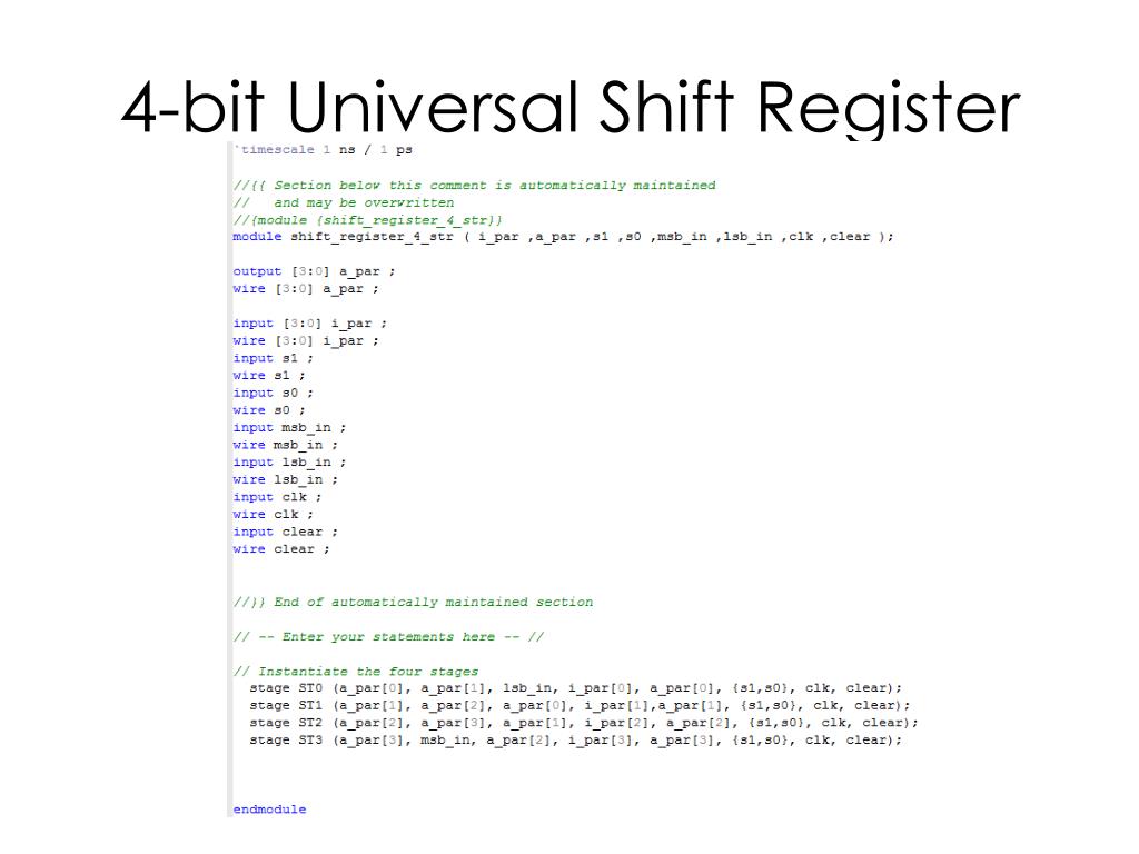

In this shift register, we can send the bits serially from the input of left most D flip-flop. All these flip-flops are synchronous with each other since, the same clock signal is applied to each one. That means, output of one D flip-flop is connected as the input of next D flip-flop. This block diagram consists of three D flip-flops, which are cascaded. The block diagram of 3-bit SISO shift register is shown in the following figure. The shift register, which allows serial input and produces serial output is known as Serial In – Serial Out (SISO) shift register. Serial In − Serial Out (SISO) Shift Register


Following are the four types of shift registers based on applying inputs and accessing of outputs. An ‘N’ bit shift register contains ‘N’ flip-flops. If the register is capable of shifting bits either towards right hand side or towards left hand side is known as shift register. The group of flip-flops, which are used to hold (store) the binary data is known as register. In order to store multiple bits of information, we require multiple flip-flops. We know that one flip-flop can store one-bit of information.


 0 kommentar(er)
